Common Path Side Viewing Monolithic Ball Lens Probe for Optical Coherence Tomography
Common path probes are highly desirable for optical coherence tomography as they reduce system complexity and cost by eliminating the need of dispersion compensation and polarization controlling optics. In this work, we demonstrate a monolithic ball lens based, common path, side viewing probe that is suitable for Fourier domain optical coherence tomography. The probe design parameters were simulated in Zemax modeling software and the simulated performance parameters were compared with experimental results. We characterized the performance of the probe by measuring its collection efficiency, resolution, and sensitivity. Our results demonstrated that with a source input power of 25 mW, we could achieve sensitivity of 100.5 dB, which is within 7 dB of the maximum possible sensitivity that could be achieved using a separate reference arm. The axial resolution of the system was found to be 15.6 µm in air and the lateral resolution (full width half maximum) was approximately 49 µm. The probe optics were assembled in a 1 mm diameter hypotube with a 500 µm inner diameter. Images of finger skin acquired using this probe demonstrated clear visualization of the stratum corneum, epidermis, and papillary dermis, along with sweat ducts.
Introduction. Optical coherence tomography (OCT) [1] is a depth-resolved, interferometric imaging modality for three-dimensional, non destructive imaging of biological tissues. OCT offers several advantages such as high axial and transverse resolutions, fast speed, and the capability to image tissue in its native state in vivo. However, the penetration depth of OCT is limited by scattering to a few millimeters and deep body tissues cannot be imaged directly. To circumvent this issue, flexible optical fiber based probes [2] are used to carry light from the source to the sample and collect the back reflected signal. With these flexible, fiber optic probes, internal organs of the body can be imaged.
Use of optical fibers in OCT is associated with several challenges. The majority of OCT systems are based on Michelson interferometer or Mach–Zehnder interferometer configurations which use separate sample and reference arms [3]. Use of fiber based interferometers with separate sample and reference arms impose several restrictive requirements on the system. First, the length of both fibers should be matched within less than a millimeter in order to detect interference between the two arms. Because it can be difficult to manufacture optical probes to this tolerance and also stretching and bending of the sample arm fiber alters the optical path, reference arm mirrors are typically mounted on a translation stage, which must be adjusted prior to imaging. The need for such stages increases the complexity and reduces ease of use of the system. Furthermore any optical fiber length mismatch between the sample and reference arms may lead to a dispersion mismatch within the fibers that can reduce sensitivity and axial resolution if not corrected numerically [3]. Second, the signal polarization states within the fibers need to be controlled in order to avoid polarization mismatch, which also degrades sensitivity [4]. For fiber optic probes that utilize standard single mode fibers (SMF), it can be difficult to control sample arm polarization, especially in clinical settings where the sample fiber is constantly bending and twisting within the patient’s body. To avoid these issues, common path probes have been proposed where the reference signal is generated near the distal tip of the probe’s sample arm fiber.
A variety of lensless common path OCT probes have been described. A simple common path probe was demonstrated where the sample arm fiber was cleaved at 0 degrees for front viewing [5] and angled polished for side viewing [6]. In this design, the Fresnel reflection from the fiber-air interface was used as reference signal. Later, a gold coated fiber tip common path probe was reported which could be used within aqueous media [7]. These lensless probes had a small working distance and relatively poor resolution at distance from the probe due to beam divergence. A conical-frustum-tip fiber common path probe [8] achieved an extended lateral resolution of the order of 4 microns but, as with the other lensless probes, the focus was predominantly near the distal tip of the probe.
Lensed common path probes have been investigated in order to better control the focal spot parameters and distance of the focus from the probe tip. Two such common path probes placed sapphire ball lens [9] and standard biconvex lenses [10] in front of the sample fiber. In these designs, the fiber-air interface acted as reference surface and the ball lens focused the light on the sample.
Another design based on a graded index (GRIN) fiber lens was proposed which included a SMF followed by glass spacer and a GRIN fiber section. The GRIN fiber-air interface acted as reference surface and the GRIN fiber comprised the focusing element. Using this design, common path, side viewing [11] and front viewing probes [12] were demonstrated. While GRIN fiber lens based common-path probes have provided excellent results, precise length control of multiple fiber elements is needed, making their fabrication challenging.
Ball lens based probes however are relatively easy to fabricate and characterize [13]. These probes can be easily modeled with standard optical simulation software and the design can be replicated in the lab with performance close to the simulated design. Any standard spherical ball lens will have Fresnel reflection from the glass-air interface which can be used as a common-path reference signal. In this paper, we describe a side viewing common path ball lens design. Our ball lens design is different from previously reported ball lens probes [9] in the way that our ball lens is fabricated directly on the fiber tip, making it a monolithic optical element. In addition, the reference surface in our design is placed at exit face of the ball lens. The monolithic common path ball lens probe is therefore easy to fabricate and does not suffer from alignment issues.
The purpose of this study was to investigate a monolithic ball lens probe design for common path optical coherence tomography. Specifically, we aimed to investigate the effect of refractive index and diameter of the ball lens on the reference power and focal spot size while maintaining a fixed focal distance from the ball lens tip.
Materials and Methods
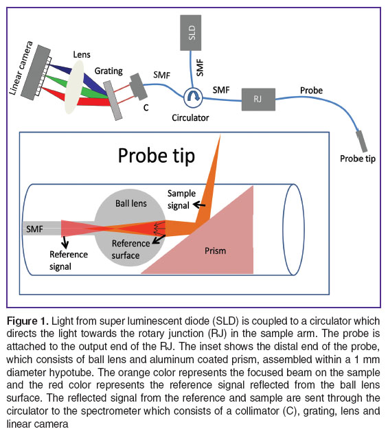
OCT system. In this work we used a spectral domain OCT system. The layout of the system is shown in Figure 1. A superluminescent diode (SLD, D-1300 HP, Superlum, Ireland) with full width half maxima (FWHM) of 50 nm around central wavelength of 1320 nm was used as light source. The output from the SLD was fed to a Booster Optical Amplifier (BOA 1130S, Thorlabs, Inc., USA) and amplified to 25 mW. The output signal from the BOA was sent to a broadband circulator (CIRC-3-31-PB, Gould Fiber Optics, USA), which was further connected to a custom-made rotary junction. Our common path probe was attached to the output port of the rotary junction. The signal collected from the probe was sent to a custom designed spectrometer (COBRA 1310, Wasatch Photonics, Inc., USA) which consisted of transmission grating (1200 lines per mm), focusing lens (f=80 mm) and InGaAs line scan camera (GL-2048-L, Sensors Unlimited, Inc., USA) with 2048 pixels. The data from the spectrometer was digitized using frame grabber (KBN-PCE-CL4-F, BitFlow, Inc., USA) over a camera link cable at line scan speed of 70 kHz. The collected data was processed using a custom designed LabVIEW (National Instruments, USA) program.
Probe design. The probe consisted of a single mode fiber (SMF-28e, Corning Inc., USA) which was connected to the custom designed rotary junction via fiber connector (E2000, Diamond USA Inc., USA). At the end of the fiber, a 125 µm diameter coreless fiber with refractive index 1.44 at 1320 nm (FG125LA, Thorlabs, Inc., USA) was spliced and molded into a ball lens using laser splicer (LZM-100, Fujikura Ltd., Japan). The ball lens surface and air interface generated Fresnel reflection which was used as reference signal. In order to make it side viewing, a 500 µm prism (66-771, Edmund Optics Inc., USA) with an aluminum coated hypotenuse was used as a side reflector.
The use of a coated prism as the reflector is an important difference between our probe and a conventional side-viewing ball lens probe. In most side viewing, non common path ball lens probes [13], the ball lens is polished at an angle to achieve total internal reflection and redirect the light at an angle with respect to the axis of the fiber. For common path ball lens probes where the reference reflection emanates from the ball lens surface, some of the reference light may not satisfy the total internal reflection condition on its way back at the polished surface and would be lost. Furthermore, there will be losses in the reference signal if there is any spatial offset between the fiber axis and center of the polished surface. To combat these potential issues, it is better to either coat the polished surface of the ball lens or use a separate reflector to deflect the beam to the side, as implemented in our common-path probe design.
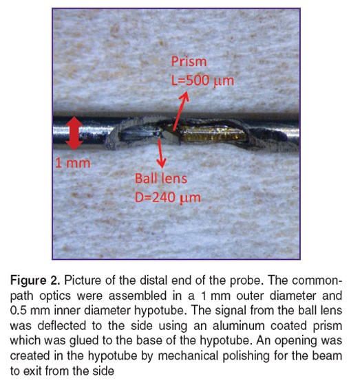
The fiber with the ball lens and prism were assembled within a hypotube (outer diameter = 1000 µm; inner diameter = 500 µm). An opening in the hypotube was created to allow the beam to exit from the side. The distal end of the probe can be seen in Figure 2.
Reference signal collection efficiency. The system was simulated using Zemax (Radiant Zemax, USA). The probe was designed to focus the beam at a distance of 2.5 mm from the ball lens tip. Since we used light reflected from ball lens surface as a reference signal, we simulated the fiber collection efficiency for the reference signal.
In order to measure the collection efficiency experimentally, we first measured the reflected signal from the illuminated probe alone. The ball lens was then dipped into index matching gel to remove Fresnel reflection from the ball lens surface. The difference in the signal measured before and after index matching gel dipping procedure was used to calculate the reference collection efficiency of the system.
Sensitivity of the system. For common path probes, sensitivity measurement is not as straightforward as measurement in non-common path systems. The standard procedure to measure sensitivity in non-common path systems involves a known reduction in the sample’s signal power [14]. The signal to noise ratio (SNR) of the system is then calculated with a mirror as the sample. The previous reduction in the sample power is doubled (because the attenuator is double-passed) and the SNR is adjusted accordingly to obtain the system’s sensitivity. However in common path probes this method cannot be applied because sample and reference signals traverse the same fiber. Any reduction in the power will affect both the reference and the sample signals. To measure the sensitivity for our system, we first measured the maximum coupling to the probe from a mirror as the sample. The mirror was then misaligned until the power in the spectrometer arm reduced by a factor of 10–4 of its initial value, which is equivalent to a 40 dB reduction in sensitivity. At this point, the SNR of the system was measured and 40 dB was added to obtain the sensitivity of our system.
Imaging. The developed probe was attached to a rotary junction and images of the finger were acquired at 70 kHz line rate. Each A-scan consisted of 1024 pixels equivalent to a distance of 5.69 mm in air.
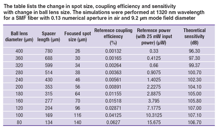
Results. The collection efficiency of the reference signal for SMF-28e fiber with numerical aperture 0.09 (0.13 in air) and focus at 2.5 mm from ball lens surface was simulated using Zemax and is listed in the Table. From the simulations we see that the collection efficiency increases as the size of the ball lens decreases (while maintaining the focus at 2.5 mm from ball lens tip). But this increase comes at the cost of reduced resolution. We also simulated the theoretical sensitivity for our system using the approach developed by Leitgeb et al. [14]. The simulated sensitivity is shown in Figure 3. The maximum sensitivity that we can achieve with our system is close to 107 dB for a ball lens diameter of 100 µm and a refractive index of 1.44. However, the focused spot size increases to 169 µm for a 100 µm ball len focused at 2.5 mm. For this work, we chose to use a ball lens of diameter 240 µm which provides a focal spot that is less than 50 µm while maintaining a sensitivity that is higher than 100 dB. The simulated collection efficiency for this ball lens was 0.0056%. The collection efficiency of our designed ball lens was measured using the method described in previous section and was found to be 0.0050%, which is close to the simulated value. With an input power of 25 mW, we achieved 1.25 µW of reference power from the ball lens surface. The maximum theoretical sensitivity at 1.25 µW reference power was estimated to be 102 dB. Experimentally, we achieved sensitivity of 100.5 dB for our designed ball lens probe which is within 2 dB of the maximum sensitivity achievable at this (1.25 µW) reference power and within 7 dB of that achievable with optimal reference power.
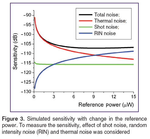 Figure 3. Simulated sensitivity with change in the reference power. To measure the sensitivity, effect of shot noise, random intensity noise (RIN) and thermal noise was considered Figure 3. Simulated sensitivity with change in the reference power. To measure the sensitivity, effect of shot noise, random intensity noise (RIN) and thermal noise was considered
|
The axial resolution of the system was measured with a mirror as the sample and was found to be 15.6 µm (FWHM), which is close to the theoretical value of 15.3 µm. The lateral resolution of the system was measured using CCD beam profiler (DataRay). The FWHM of the focused beam at a distance of 2.5 mm from the ball lens surface was 49 µm and closely matched to the Zemax simulation results.
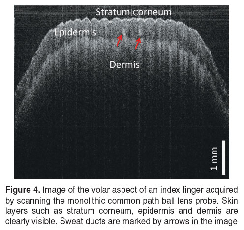
An image of the volar aspect of an index finger is shown in Figure 4. In this image we can see different layers of the skin such as stratum corneum, epidermis and dermis up to a penetration depth of 1.5 mm. One can also notice the presence of sweat ducts traversing the epidermis of the skin.
Discussion and Conclusion. In this work we have demonstrated a monolithic ball lens common path probe for OCT imaging. The ball lens probe is easy to fabricate using a laser splicer. The reference power from the ball lens’ surface can be increased by decreasing the ball lens diameter to tailor the sensitivity of the system; however, decreasing the ball lens’ diameter while maintaining the focal distance compromises the resolution of the system. A fixed focal distance from the ball lens tip requires smaller spacer length when the ball lens diameter is decreased, which limits the distance for the beam to expand. A smaller beam diameter at the ball lens reduces the numerical aperture of the ball lens and results in a larger focal spot. We found that with the appropriate selection of parameters, including spacer and ball lens diameter, one can achieve close to shot noise limited common path detection for spectral domain OCT. A further advantage of our probe is that it is monolithic, potentially making it less vulnerable to breakage during clinical application.
An alternative method for increasing the reference power from the ball lens’ surface would be to use a higher refractive index material to fabricate the ball lens. For instance, for the same focal spot size of 46 µm at 2.5 mm from the fiber tip and 25 mW input power, the simulated reference power is 1.40 µW for fused silica (n=1.44) ball lens, 2.4 µW for N-BK7 (n=1.50) ball lens and 16.75 µW for S-LAH64 (n=1.76) ball lens at 1320 nm. The increase in reference power is primarily because of two reasons, first, higher refractive index gives larger Fresnel reflection at the ball lens air boundary and secondly, reference coupling efficiency is better for ball lenses with higher refractive indices.
Based on these features and the capability of common path probes to provide a simpler solution for OCT, we believe that this development will be an enhancement for certain types of catheter and needle-based OCT systems.
Study Funding. Fonds de recherche du Québec–Santé (Postdoctoral fellowship, K. Singh); Canon USA, Inc., USA.
Conflict of Interests. Dr. Tearney receives sponsored research funding from Canon USA, Inc. Drs. Tearney and Singh have written patents that are licensed to Canon USA, Inc. Drs. Tearney and Singh have the rights to receive royalties as part of this licensing arrangement. Mr. Yamada is an employee of Canon USA, Inc.
References
- Huang D., Swanson E.A., Lin C.P., Schuman J.S., Stinson W.G., Chang W., et al. Optical coherence tomography. Science 1991; 254(5035): 1178–1181, http://dx.doi.org/ 10.1126/science.1957169.
- Sergeev A.M., Gelikonov V.M., Gelikonov G.V., Feldchtein F.I., Kuranov R.V., Gladkova N.D., et al. In vivo endoscopic OCT imaging of precancer and cancer states of human mucosa. Opt Express 1997; 1(13): 432–440, http://dx.doi.org/10.1364/OE.1.000432.
- Wojtkowski M., Srinivasan V.J., Ko T.H., Fujimoto J.G., Kowalczyk A., Duker J.S. Ultrahigh-resolution, high-speed, Fourier domain optical coherence tomography and methods for dispersion compensation. Opt Express 2004; 12(11): 2404–2422, http://dx.doi.org/10.1364/OPEX.12.002404.
- Saxer C.E., de Boer J.F., Park B.H., Zhao Y., Chen Z., Nelson J.S. High-speed fiber based polarization-sensitive optical coherence tomography of in vivo human skin. Opt Lett 2000; 25(18): 1355–1357, http://dx.doi.org/10.1364/ol.25.001355.
- Zhang K., Kang J.U. Common-path low-coherence interferometry fiber-optic sensor guided microincision. J Biomed Opt 2011; 16(9): 095003, http://dx.doi.org/10.1117/1.3622492.
- Sharma U., Kang J.U. Common-path optical coherence tomography with side-viewing bare fiber probe for endoscopic optical coherence tomography. Rev Sci Instrum 2007; 78(11): 113102, http://dx.doi.org/10.1063/1.2804112.
- Han J.-H., Ilev I.K., Kim D.-H., Song C.G., Kang J.U. Investigation of gold-coated bare fiber probe for in situ intra-vitreous coherence domain optical imaging and sensing. Appl Phys B 2010; 99(4): 741–746, http://dx.doi.org/10.1007/s00340-010-3910-4.
- Ji-hyun Kim, Jae-Ho Han, Jichai Jeong. Common-path optical coherence tomography using a conical-frustum-tip fiber probe. IEEE J Select Topics Quantum Electron 2014; 20(2): 8–14, http://dx.doi.org/10.1109/jstqe.2013.2277817.
- Zhao M., Huang Y., Kang J.U. Sapphire ball lens-based fiber probe for common-path optical coherence tomography and its applications in corneal and retinal imaging. Opt Lett 2012; 37(23): 4835–4837, http://dx.doi.org/10.1364/OL.37.004835.
- Gelikonov V.M., Gelikonov G.V. New approach to cross-polarized optical coherence tomography based on orthogonal arbitrarily polarized modes. Laser Phys Lett 2006; 3(9): 445–451, http://dx.doi.org/10.1002/lapl.200610030.
- Lorenser D., Quirk B.C., Auger M., Madore W.-J., Kirk R.W., Godbout N., et al. Dual-modality needle probe for combined fluorescence imaging and three-dimensional optical coherence tomography. Opt Lett 2013; 38(3): 266–268, http://dx.doi.org/10.1364/OL.38.000266.
- Mao Y., Chang S., Sherif S., Flueraru C. Graded-index fiber lens proposed for ultrasmall probes used in biomedical imaging. Appl Opt 2007; 46(23): 5887–5894, http://dx.doi.org/10.1364/AO.46.005887.
- Yang V.X.D, Mao Y.X., Munce N., Standish B., Kucharczyk W., Marcon N.E., Vitkin I.A. Interstitial Doppler optical coherence tomography. Opt Lett 2005; 30(14): 1791–1793, http://dx.doi.org/10.1364/OL.30.001791.
- Leitgeb R., Hitzenberger C., Fercher A. Performance of fourier domain vs. time domain optical coherence tomography. Opt Express 2003; 11(8): 889–894, http://dx.doi.org/10.1364/OE.11.000889.
