Intra- and Inter-Frame Differential Doppler Optical Coherence Tomography
Spectrometer based optical coherence tomography suffers from fringe washout for fast flow, a drawback for flow visualization, which is of interest for both lable-free optical angiography and flow quantification. We presented a method, which can be used to contrast very fast flows, while maintaining relatively low A-scan rates. It is based on introducing a phase shift of  during acquisition such that the interference fringes associated to moving sample structures are recovered depending on the axial velocity. This enables the use of slower line scan cameras for measuring the fast blood flows within the large vessels in the region of the optic nerve head, while keeping good sensitivity. Furthermore it can be used to contrast the fast moving structures by attenuating the static and slower moving tissue signals. A drawback is still the narrow velocity bandwidth, which is not optimal for providing optical angiography for the full vascular plexus. Nevertheless, it could be of value for following fast dynamic changes, as for example in optical elastography. We introduce different variants of this method, based on intra-frame phase switching, as well as between consecutive A-scans and B-scans, which are then pairwise summed. A phase shift of
  between summed scans is in fact equivalent to subtraction of both in general complex valued scans. Analyzing complex signal differences between successive B-scans allows in particular contrasting very slow flows of the capillary network. After setting the theoretical framework we show proof-of-principle measurements with a piezo mirror, as well as in vivo measurements of the human retina for the different intra-frame phase shifting schemes. We further show the capability to contrast the parafoveal capillary structure with the differential inter B-scan method and discuss its limitations. Improvement of the sensitivity might be achieved by increasing the number of B-scans to be used for calculating the signal differences, as well as by increasing the sampling density. Care must then be taken for in vivo imaging to keep the total measurement time still sufficiently small, typically a few seconds. The method may proof as a valuable diagnostic tool, as several retinal diseases will manifest at an early stage in capillary disorders.
Introduction. Over the past years spectral domain OCT (SD-OCT) has proven its value in the field of ophthalmology [1, 2]. Its ability to acquire three dimensional image date, with micrometer resolution, high sensitivity, and high speed makes it an important diagnostic tool [3–6]. Also functional extensions of OCT, such as Doppler OCT, have proven to provide additional information for the diagnosis of several major retinal diseases [7, 8]. Doppler OCT allows measuring the speed of moving particles quantitatively with high precision. Most commonly the phase difference between successive A-scans is calculated in order to retrieve the phase shift introduced by a particle moving parallel to the probing beam [9, 10]. Recent developments aim at optical angiography as a lable-free alternative to fluorescein or indocyanine green angiography. An intrinsic drawback of SD-OCT based on spectrometer detection is the occurrence of signal-to-noise ratio (SNR) loss for structures at motion, due to the blurring of the associated interference fringes [11, 12]. This significantly limits the utility for visualizing and quantifying flow with Doppler OCT. Regions with fast flow such as in large vessels at the optic nerve head experience missing signal which then alters quantitative flow readings. Recent en-face Doppler OCT has been demonstrated to be independent on the Doppler angle, but works best in steep vessels with well defined en-face cross sections [13, 14]. Only high-speed OCT setups are then capable to reduce those artifacts for reliable flow assessment but come with a reduction in detection sensitivity [15]. Possible counter measures have been taken by assuming a laminar flow and by interpolating missing flow signatures based on a parabolic flow profile [16]. For large vessels this assumption is well justified, but needs to be taken with care for vessel calibers smaller than 100 µm. A first step towards mitigating this artifact has been resonant Doppler imaging [12]. There, the reference arm length is actively changed during acquisition, such that structures in the sample arm that move axially with the same velocity do not experience fringe blurring. This is due to the fact that the relative distance between sample structure at motion and reference arm mirror remains constant during acquisition. This has been well used to contrast flow against static tissue thereby generating a label-free optical angiography picture. The interesting feature of this method is the possibility to visualize structures that move at fast speed, and would be virtually invisible to standard SD-OCT detection systems. In the present paper we introduce an even simpler method to achieve sensitivity to rapidly moving sample structures by introducing a constant  phase offset during acquisition or in-between acquisitions. The particular advantage of the following method is the possibility to use lower acquisition speeds and thereby maintaining good detection sensitivity. A variant of this method that analyses subsequent tomograms with relative
  shift has been successfully used to contrast tissue vasculature with high sensitivity.
Methods
Intra-frame differential Doppler OCT principle. The principle is based on introducing a  -phases hift in the reference arm during camera exposure. This phase shift is introduced by applying the half-wave voltage
  to an electro-optic modulator (EOM) placed in the reference arm. The EOM allows precise synchronization with the camera even at fast frame rates. Let us assume without loss of generality a single interface in the sample and reference arm. We further concentrate on the cross-correlation signal between sample and reference arm light that is recorded as spectral interference pattern in SD-OCT. Fourier transform of the interference pattern yields the depth structure of the sample, or A-scan. If the reference arm length is switched by
  after half of the exposure time of the spectral interference signal, the integration over the full exposure time will average out the fringe pattern. Here, n is the refractive index of the reference arm medium, and
  is the center wavelength of the employed light source. However, if the sample interface is moving axially, an additional net phase shift between sample and reference arm is introduced during acquisition. This causes incomplete loss up to full recovery of the integrated fringe signal, depending on the sample speed. Thus the sample signal after Fourier transform associated to the interface at motion will again be visible. The spectral interferogram can be written as a function of number of generated photo-electrons N by

with  being the camera exposure time,
  the proportionality factor, accounting for the detector efficiency, IR,S(k) the spectral intensities of sample and reference arm respectively that reach the detector, φ(t) the time dependent phase shift between reference and sample signal,
  the pathlength difference between sample and reference arm at t=0, and k is the wavenumber. Following Yun et al. [11], we can write

Δφ is the total phase change during the camera exposure time. In case of constant axial velocity  of the sample interface during exposure, the phase φ(t)=2
 , and the accumulated phase during exposure time becomes Δφ=φ
 , assuming 100% duty cycle and
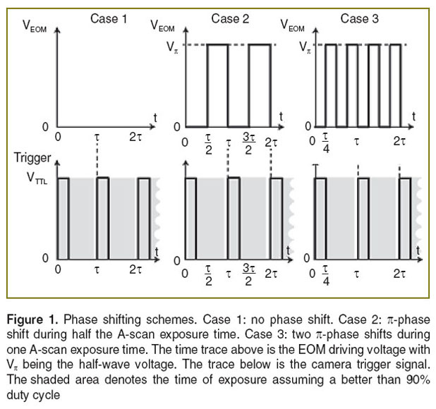
  (Figure 1 (case 1)). Resonant Doppler imaging is a way to shift the sinc-shaped attenuation curve to higher velocities, which then can be assessed also quantitatively via Doppler OCT.
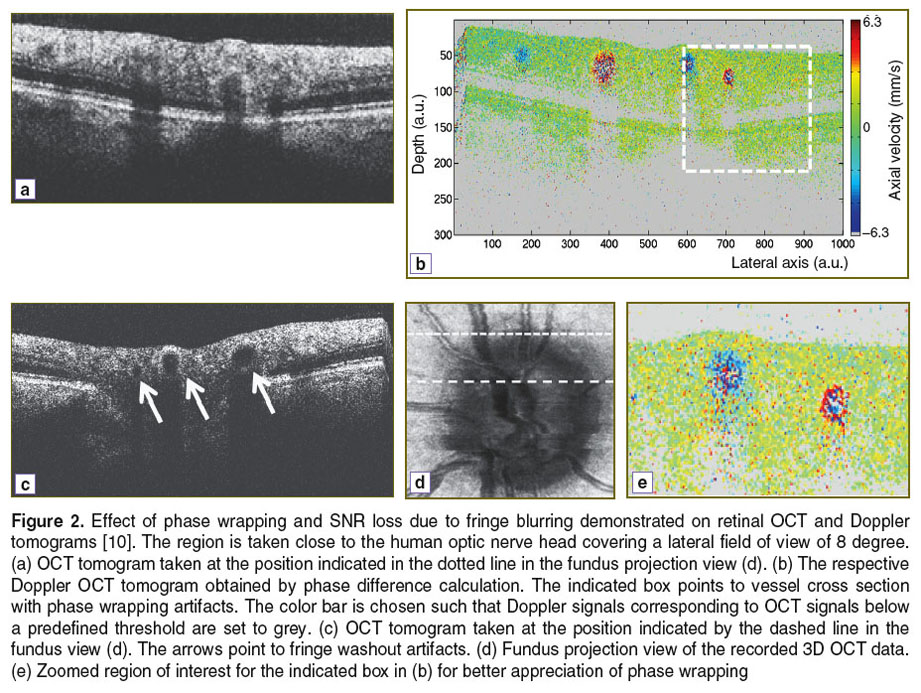
In Doppler OCT the unambiguous velocity range is determined by the exposure time or A-scan period time as  If the actual velocity is exceeding the unambiguous velocity range, phase wrapping occurs (Figure 2 (a) and (b)). For large axial velocities fringe washout will lead to complete signal loss as shown in Figure 2 (c).
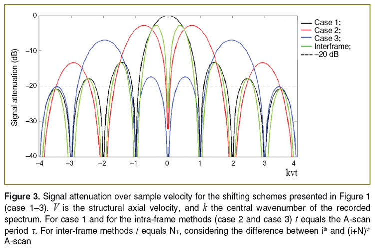
According to Figure 3 (case 1) several phase wrappings can be seen before the signal itself will vanish below the noise floor due to fringe blurring. This depends mainly on the original SNR of the structure, if it was at rest. The assessable velocity range can be extended by correcting phase wrapping artifacts in post processing [16]. SNR loss can only be corrected for by assuming laminar flow, which for example excludes important effects in blood vessels such as the flow profile blunting due to the Fahraeus–Lindqvist effect [17, 18]. Figure 2 shows the effect of SNR loss due to fringe blurring in case of large velocities, as well as the effect of phase wrapping. The SNR of flow signatures is below 20 dB. The image represents a Doppler OCT tomogram, with colors encoding the axial velocities. The Doppler OCT tomogram is obtained by calculating signal phase differences between adjacent A-scans.
Consider now the case, where we introduce a phase shift of  by applying the potential
  during one half of the exposure time. It will result in the following signal (Figure 1 (case 2)):

with sinc(x)=sin(x )/x
)/x . We observe in addition to thesinc-function as in the previous case a sine-dependence of the total intensity on the total phase change Δφ=φ
 . This now has several implications: first, the signal for structures at rest and for slowly moving structures is below the noise floor, thus not visible. We may assume a theoretic noise floor of –20 dB below the theoretic maximum SNR
  =0 at without phase shifting applied. Secondly, the signal strength scales in first order linearly with the axial velocity of the sample structure. This allows contrasting moving structures from structures at rest, i.e., performing optical angiography. On the other hand, knowing the exact signal attenuation with respect to the case without differential
  -shift during acquisition allows for quantitative axial velocity measurement. The respective intensity dependence is plotted in Figure 3 (case 2). Note that Figure 3 plots all signal amplitude curves normalized to their value at
  =0, i.e., the amplitude of the structure when it would be at rest, and without phase shifting applied. The full strength comes in when analyzing more general phase shifting patterns, that equally lead to vanishing static structure terms. In fact we might shorten the duration of applying
  to
to  /4. The phase φ(t) would then be altered by switching between
  =0 and
  during acquisition after intervals of
  /4. The signal becomes

Figure 3 shows the amplitude attenuation for the single (case 2) and double (case 3) phase switching schemes (See Figure 1). One observes that the velocity range, for which structures at motion are well visible, appears shifted with increased splitting of the full acquisition time. Another observation is the axial shift  in the structure term, that contains the dependency on
  . In order to extend the velocity range, one could in principle also mix the different interval schemes, for example using for the first half of the acquisition time single phase shifting pattern, and for the second halve the double shifting pattern. Note that Figure 3 does not take into account SNR loss due to signal decorrelation for example due to lateral scanning [19].
Inter-frame differential Doppler OCT principle. The  -shifting method can equally be applied to successive A-scans or even of B-scans, called inter-frame differential Doppler OCT. Whereas, intra-frame phase shifting extends the assessable velocity range beyond the limits given by the acquisition speed of the camera, the inter-frame methods aim at contrasting structures at motion from static structures. This is used for performing label-free optical angiography, where structures at motion are red blood cells. Basically the visibility of flow signatures is not only determined by fringe blurring. The smallest resolvable velocity is given by the system phase difference noise
  according to
  . In shot noiselimited detection systems the phase noise is in turn determined by the SNR as
  [19]. From
  we observe that increasing the A-scan period time
  results in higher velocity sensitivity. However, if the
  is increased the signal correlation between successively recorded A-scans will be reduced and ultimately lost. Angiography can be achieved basically in two domains: in the correlated domain one aims at contrasting blood flow via observing Doppler OCT signature visible in phase difference tomograms. For this, it is necessary that the time between analyzed signals is chosen such that the signal remains correlated. The fully quantitative angiography is obtained then by signal post-processing using for example histogram-based methods [20, 21], or by spatial frequency filtering [22, 23], or by calculating the phase variance [24]. The second domain is based on observing signal decorrelation. For this, the period
  must be sufficient large.
Introducing a phase shift of between successive frames is in fact easily achieved by observing that cos(x+ )=–cos(x). Hence, subtraction of the signals will have the same effect as phase shifting by
  similar to case 2 in Figure 1 and according to Eq. 3 with Δφ as the argument of the sine-function instead of Δφ/2. The A-scan difference can be equally taken already in the wavenumber or spectral domain between successively recorded interference patterns. Clearly, both A-scans are equally affected by fringe washout, the amplitude attenuation curve of the difference signal as function of sample velocity will therefore exhibit the same zeros as the sinc-function for the single A-scan case (See Figure 3 (case 1)). Close to zero the subtraction scheme causes again vanishing of static signal, which allows for contrasting of flow with velocities in the order
  /4
/4 of with
  the A-scan period time.
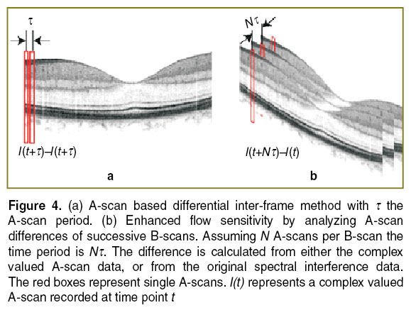
In case of capillary flow, one aims at time differences of one to several milliseconds. Obviously increasing the time between A-scans would ultimately increase the recording time for a full tissue volume to several tens of seconds. This should be avoided forin vivo assessment, as motion artifacts would lead to strong structural distortions of the recorded images. A solution is to consider successive B-scans or tomograms (Figure 4) [25]. In case of inter-B-scan analysis, the time between successive B-scans will be N , with N the number of A-scans that comprise the B-scan.This improves the velocity sensitivity, as the minimal resolvable velocity scales inversely proportional with the time period. The filter characteristic will again be determined by Eq. 3, but now with NΔφ as the argument of the sine-function.
In general for inter-frame differential Doppler OCT the signal becomes

The corresponding signal attenuation with increasing axial velocity is plotted in Figure 3. With high-speed OCT systems the time between tomograms can be adjusted to a few milliseconds and below. Other variants use parts of B-scans to achieve appropriate time intervals [25, 26]. For small velocities the attenuation curve scales with  2, allowing therefore a sharper filtering between static and moving structures than using for example a simple Gaussian filter model [20, 21].
As for the intra-frame technique one could equally combine data sets processed with different time intervals between analyzed A-scans. As seen from Figure 3 (green curve) the width of the first lobe in the respective attenuation curve scales with the time interval T, thus the effective bandwidth could be enhanced.
Optical setup. The optical setup is displayed in Figure 5. Light from a Ti:Sapph laser at a center wavelength of  =820 nm and a bandwidth of 75 nm is delivered to the Mach–Zehnder interferometer via fiber collimator. It passes a polarizer set parallel to the fast axis of the EOM in the reference arm. The polarization controller in the delivery fiber allows adjusting the output state such that the power after the polarizer is maximum. In the sample arm dispersion prism pairs match the dispersion of the crystal in the EOM as well as the dispersion of the eye for retinal imaging. The light is scanned across the sample via galvo scanners (x/y scan). The telescope consisting of two achromats (L1, L2) in front of the eye produces a focused spot on the retina. Finally, the light from the sample and the reference arm is coupled back into a fiber and guided to a spectrometer. The spectrometer is equipped with a line array sensor (Basler sprint, 12 bit) with 1500 pixels actively read-out. The power at the cornea is set to 700 µW. The recorded spectrum allows for a theoretical axial resolution of 4 µm in air.
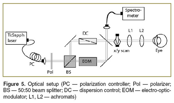 Figure 5. Optical setup (PC — polarization controller; Pol — polarizer; BS — 50:50 beam splitter; DC — dispersion control; EOM — electro-optic-modulator; L1, L2 — achromats) Figure 5. Optical setup (PC — polarization controller; Pol — polarizer; BS — 50:50 beam splitter; DC — dispersion control; EOM — electro-optic-modulator; L1, L2 — achromats)
|
Results and Discussion. For a proof of principle we first experimentally verified the theoretical curves shown in Figure 3 by using a mirror mounted on a loudspeaker in the sample arm. The oscillating mirror experiences different axial velocities depending on oscillation frequency and amplitude. The frequency was chosen such that the oscillation could be well resolved by the sampling due to the A-scan rate. We recorded an M-scan consisting of 1000 A-scans taken at the same position at the sample mirror with an A-scan rate of 30 kHz. The respective maximum unambiguous axial velocity would be ±6.2 mm/s. For plotting the attenuation curve, we first calculated the phase differences  between adjacent A-scans and applied phase unwrapping. The phase differences can then be associated to velocities according to
  . Finally, we normalized the intensity tomograms to the signal for the mirror at rest and plot for each time point the normalized signal amplitude versus the associated axial velocity at that instant. This results in the attenuation values plotted in Figure 6 together with the theoretically expected curves. We first recorded the signal without phase shifting scheme shown in Figure 6 (lhs). The measured values fit well with the expected sinc-shaped signal loss due to fringe blurring. We then verified experimentally the case of single
  -shift (See Figure 1 (case 2)) during half of the exposure times shown in Figure 6 (rhs).
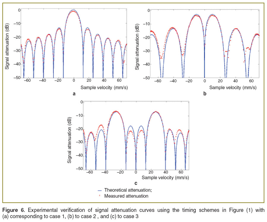 Figure 6. Experimental verification of signal attenuation curves using the timing schemes in Figure (1) with (a) corresponding to case 1, (b) to case 2, and (c) to case 3 Figure 6. Experimental verification of signal attenuation curves using the timing schemes in Figure (1) with (a) corresponding to case 1, (b) to case 2, and (c) to case 3
|
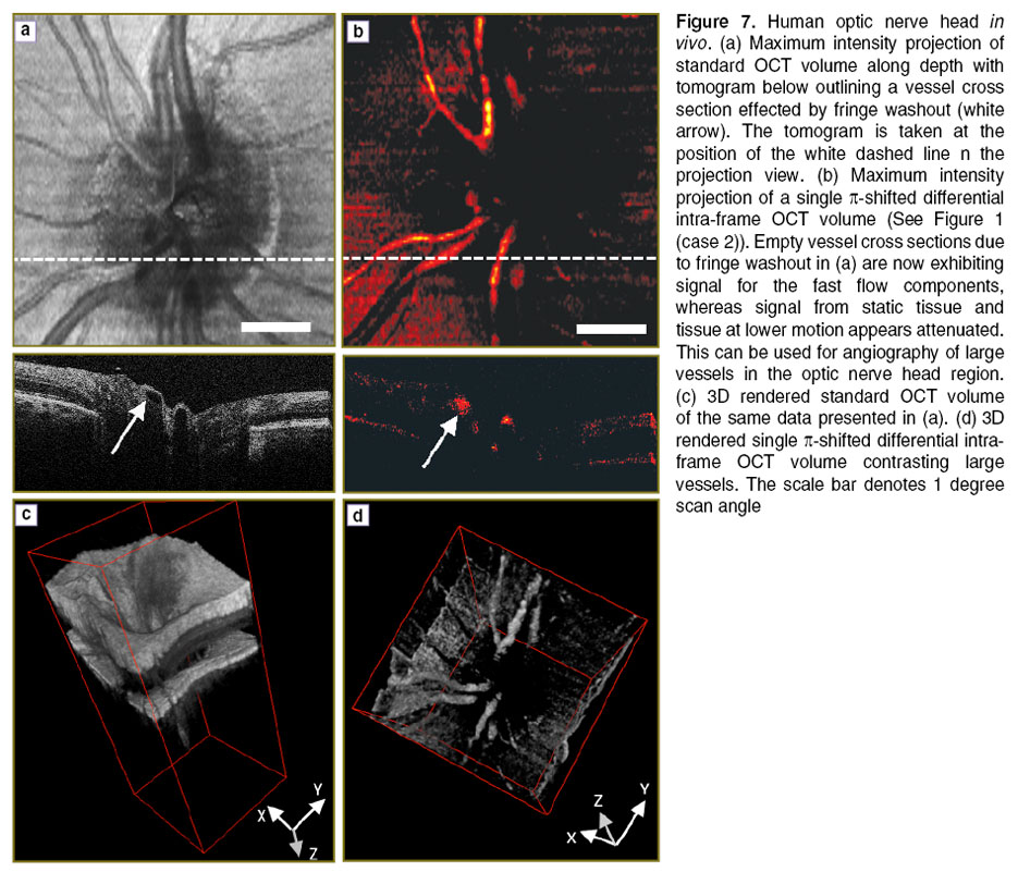
To demonstrate that this method is applicable for in vivo measurements, we performed measurements of the human retina of a healthy volunteer. The in vivo measurements have been performed in compliance with the local ethics committee regulations and the declaration of Helsinki. Informed consent of the volunteer has been obtained. The first measurement was performed at 30 kHz A-scan rate covering the region of the optic nerve head. This region is characterized by large vessels that ascend and radially enter the retina. The flow within those vessels is large and causes significant fringe washout and signal loss. One recorded volume contains 100 B-scans, each consisting of 1000 A-scans. Figure 7 (a) shows a maximum intensity projection of volume intensity data obtained with a standard OCT scanning configuration without phase shifting (See Figure 2 (case 1)). The white dashed line indicates the position where the B-scan shown below is extracted. Two large vessels that appear empty are visible in the center of the B-scan. The arrow points to those areas that exhibit strong fringe washout and signal loss. Figure 7 (b) shows a measurement with a single  -shift during the exposure corresponding to case 2 in Figure 2. Significant signal attenuation of the static tissue can be observed. Comparison of the tomogram sections in Figure 7 (a) and (b) nicely demonstrates the recovery of the originally lost signal due to the fast moving blood by employing the simple
  -shifting technique (white arrow). Figure 7 (c) and (d) demonstrate the capability to perform 3D angiography with based on the differential phase shifting technique. Whereas the vessels are obscured by the embedding scattering tissue in Figure 7 (c) they are clearly contrasted in Figure 7 (d). Of course the
  -shifting enhances only structures that move within a finite bandwidth of axial velocities as plotted in Figure 3. Thus the signal of smaller vessels with corresponding smaller flow velocities will be equally attenuated. This limits the technique for its applicability to optical angiography, where it is desirable to visualize the full vascular plexus. However, it is of advantage when specific vessels are to be assessed with an OCT system that is limited in A-scan rate. The intra-frame differential OCT modality provides then a method to overcome the problems of fringe washout in case of large axial velocities and to allow quantitative assessment of those flows.
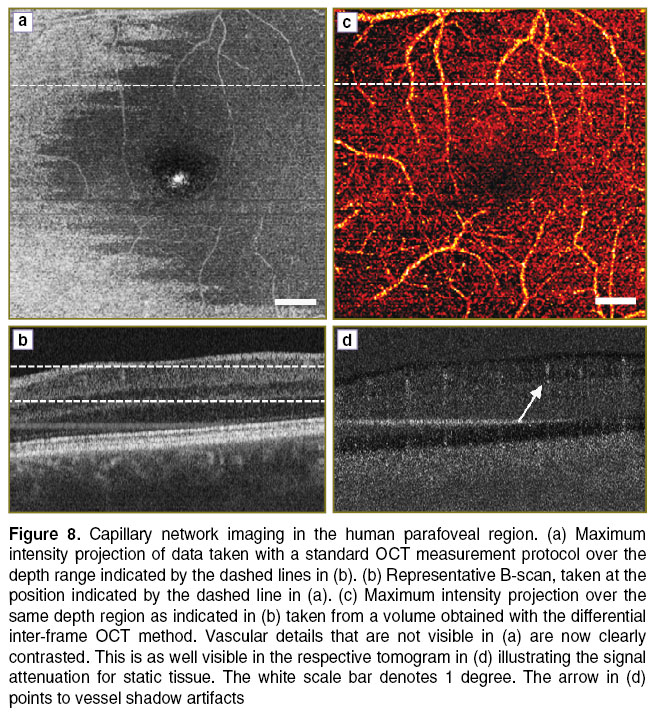
In contrast, the inter-frame differential OCT method has the capability of visualizing very slow flowing structures as present in small capillaries. For demonstration we imaged the capillary network surrounding the human fovea with a standard OCT measurement protocol and did first standard OCT signal processing, and then with the inter-frame method applied, by calculating A-scan differences of successive B-scans. The volume was recorded at an A-scan rate of 100,000 A-scans/s and contained 400 B-scans, each consisting of 400 A-scans, resulting in a B-scan rate of 250 Hz. Two B-scans are recorded at the same vertical position. Figure 8 (a) shows a fundus projection of a volume taken at the parafoveal region with the standard OCT processing. Some vessels are visible due to the strong scattering of red blood cells, but the capillaries are obscured by the embedding scattering tissue. The dashed line indicates the position for the extracted tomogram in Figure 8 (b).
Figure 8 (c) and (d) presents the result by employing the inter-frame differential OCT modality, based on taking the signal difference between successive B-scans (See Figure 4). Prior to taking the signal difference, axial registration of the B-scans has been performed using the position of the maximum of the cross-correlation as axial displacement correction. In the present case we calculated the difference between those B-scans taken at the same vertical position. Figure 8 (c) shows a maximum intensity projection taken from the difference volume ranging from the ganglion cell layer down to the inner plexiform layer. The individual capillaries are now well appreciated. The B-scan in Figure 8 (d) illustrates the signal attenuation of static tissue, while the signal from the capillaries is maintained. A common effect to highly sensitive motion contrast methods is the appearance of vessel shadows due to multiple scattering and speckle decorrelation of light passing through the flow regions. They can be reduced for example by intensity masking or by employing Bessel beams [27, 28]. Still, the smallest capillaries at the center are not well resolved. This could be improved by either increasing the number of B-scans per position, or by increasing the lateral sampling [29]. One needs however to consider that the resulting increased measurement time causes motion artifacts that might destroy the structural integrity of the displayed images. Also, complex signal analysis might require correction of phase changes due to involuntary axial bulk motion, which has not been done for the present data set. Simple intensity based difference methods to contrast flow are therefore easier to implement, as they only require careful tomogram registration [30].
In conclusion we presented a method, which can be used to contrast very fast flows, while maintaining relatively low A-scan rates. This enables the use of slower line scan cameras for measuring the fast blood flows within the large vessels in the region of the optic nerve head, while keeping good sensitivity. Furthermore it can be used to contrast the fast moving structures by attenuating the static and slower moving tissue signals. A drawback is still the narrow velocity bandwidth, which is not optimal for providing optical angiography for the full vascular plexus. Nevertheless, it could be of value for following fast dynamic changes, as for example in optical elastography. Furthermore, spectroscopy based OCT provides higher phase stability than swept source OCT system. The differential intra-frame technique is a way to avoid intrinsic fringe washout and keep the high sensitivity for following dynamic structural changes. Apart from biological tissue the method might be equally useful to be applied to industry applications. A modification of this method to analyzing complex signal differences between successive B-scans was used to contrast very slow flows of the capillary network. The latter has equally been termed UHS-OMAG [31] and is further the basis of dynamic light scattering [32]. Improvement of the sensitivity might be achieved by increasing the number of B-scans to be used for calculating the signal differences, as well as by increasing the sampling density. Care must then be taken for in vivo imaging to keep the total measurement time still sufficiently small, typically a few seconds. The method may proof as a valuable diagnostic tool, as several retinal diseases will manifest at an early stage in capillary disorders.
Acknowledgements. We acknowledge financial support from the European Commission Seventh Framework FP7-HEALTH program (grant 201880, FUN OCT). I.R.I. acknowledges support by the Ernst-Mach Scholarship of the Austrian Federal Ministry of Science, Research, and Economy. The authors thank Laurin Ginner for helping to prepare manuscript figures.
Conflict of Interest. The authors declare no conflict of interest with the content of the present research paper.
References
- Wojtkowski M., Leitgeb R., Kowalczyk A., Bajraszewski T., Fercher A.F. In vivo human retinal imaging by Fourier domain optical coherence tomography. J Biomed Opt 2002; 7(3); 457–463, http://dx.doi.org/10.1117/1.1482379.
- Drexler W., Leitgeb R., Hitzenberger C.K. New developments in optical coherence tomography technology. In: Medical Retina. Holz F.G., Spaide R. (eds.). Springer Berlin Heidelberg; 2010; p. 201–216, http://dx.doi.org/10.1007/978-3-540-85540-8_17.
- Leitgeb R., Hitzenberger C.K., Fercher A.F. Performance of fourier domain vs. time domain optical coherence tomography. Opt Express 2003; 11(8): 889–894, http://dx.doi.org/10.1364/OE.11.000889.
- Wojtkowski M., Srinivasan V.J., Ko T.H., Fujimoto J.G., Kowalczyk A., Duker J.S. Ultrahigh-resolution, high-speed, Fourier domain optical coherence tomography and methods for dispersion compensation. Opt Express 2004; 12(11): 2404–2422, http://dx.doi.org/10.1364/OPEX.12.002404.
- Leitgeb R.A., Drexler W., Unterhuber A., Hermann B., Bajraszewski T., Le T., Stingl A., Fercher A.F. Ultrahigh resolution Fourier domain optical coherence tomography. Opt Express 2004; 12(10): 2156–2165, http://dx.doi.org/10.1364/OPEX.12.002156.
- Nassif N., Cense B., Park B.H., Yun S.H., Chen T.C., Bouma B.E., Tearney G.J., de Boer J.F. In vivo human retinal imaging by ultrahigh-speed spectral domain optical coherence tomography. Opt Letters 2004; 29(5): 480–482, http://dx.doi.org/10.1364/OL.29.000480.
- Leitgeb R.A., Werkmeister R.M., Blatter C., Schmetterer L. Doppler optical coherence tomography. Prog Retin Eye Res 2014; 41: 26–43, http://dx.doi.org/10.1016/j.preteyeres.2014.03.004.
- Wang Y., Fawzi A.A., Varma R., Sadun A.A., Zhang X., Tan O., Izatt J.A., Huang D. Pilot study of optical coherence tomography measurement of retinal blood flow in retinal and optic nerve diseases. Invest Ophthalmol Vis Sci 2011; 52(2): 840–845, http://dx.doi.org/10.1167/iovs.10-5985.
- Zhao Y., Chen Z., Saxer C., Xiang S., de Boer J.F., Nelson J.S. Phase-resolved optical coherence tomography and optical Doppler tomography for imaging blood flow in human skin with fast scanning speed and high velocity sensitivity. Opt Letters 2000; 25(2): 114–116, http://dx.doi.org/10.1364/ol.25.000114.
- Leitgeb R.A., Schmetterer L., Drexler W., Fercher A.F., Zawadzki R.J., Bajraszewski T. Real-time assessment of retinal blood flow with ultrafast acquisition by color Doppler Fourier domain optical coherence tomography. Opt Express 2003; 11(23): 3116–3121, http://dx.doi.org/10.1364/oe.11.003116.
- Yun S.H., Tearney G.J., de Boer J.F., Bouma B.E. Motion artifacts in optical coherence tomography with frequency-domain ranging. Opt Express 2004; 12(13): 2977–2998, http://dx.doi.org/10.1364/OPEX.12.002977.
- Bachmann A.H., Villiger M.L., Blatter C., Lasser T., Leitgeb R.A. Resonant Doppler flow imaging and optical vivisection of retinal blood vessels. Opt Express 2007; 15(2): 408–422, http://dx.doi.org/10.1364/OE.15.000408.
- Baumann B., Potsaid B., Kraus M.F., Liu J.J., Huang D., Hornegger J., Cable A.E., Duker J.S., Fujimoto J.G. Total retinal blood flow measurement with ultrahigh speed swept source/Fourier domain OCT. Biomed Opt Express 2011; 2(6): 1539–1552, http://dx.doi.org/10.1364/BOE.2.001539.
- Schmoll T., Leitgeb R.A. Heart-beat-phase-coherent Doppler optical coherence tomography for measuring pulsatile ocular blood flow. J Biophotonics 2013; 6(3): 275–282, http://dx.doi.org/10.1002/jbio.201200029.
- Schmoll T., Kolbitsch C., Leitgeb R.A. Ultra-high-speed volumetric tomography of human retinal blood flow. Opt Express 2009; 17(5): 4166–4176, http://dx.doi.org/10.1364/OE.17.004166.
- Singh A.S.G., Kolbitsch C., Schmoll T., Leitgeb R.A. Stable absolute flow estimation with Doppler OCT based on virtual circumpapillary scans. Biomed Opt Express 2010; 1(4): 1047–1059, http://dx.doi.org/10.1364/BOE.1.001047.
- Fahraeus R., Lindqvist T. The viscosity of the blood in narrow capillary tubes. Am J Physiol 1931; 96: 562–568.
- Moger J., Matcher S.J., Winlove C.P., Shore A. Measuring red blood cell flow dynamics in a glass capillary using Doppler optical coherence tomography and Doppler amplitude optical coherence tomography. J Biomed Opt 2004; 9(5): 982–994, http://dx.doi.org/10.1117/1.1781163.
- Park B.H., Pierce M.C., Cense B., Yun S.-H., Mujat M., Tearney G.J., Bouma B.E., de Boer J.F. Real-time fiber-based multi-functional spectral-domain optical coherence tomography at 1.3 µm. Opt Express 2005; 13(11): 3931–3944, http://dx.doi.org/10.1364/opex.13.003931.
- Kolbitsch C., Schmoll T., Leitgeb R.A. Histogram-based filtering for quantitative 3D retinal angiography. J Biophotonics 2009; 2(6–7): 416–425, http://dx.doi.org/10.1002/jbio.200910026.
- Singh A.S.G., Schmoll T., Leitgeb R.A. Segmentation of Doppler optical coherence tomography signatures using a support-vector machine. Biomed Opt Express 2011; 2(5): 1328–1339, http://dx.doi.org/10.1364/boe.2.001328.
- Tao Y.K., Davis A.M., Izatt J.A. Single-pass volumetric bidirectional blood flow imaging spectral domain optical coherence tomography using a modified Hilbert transform. Opt Express 2008; 16(16): 12350–12361, http://dx.doi.org/10.1364/oe.16.012350.
- An L., Wang R. K. In vivo volumetric imaging of vascular perfusion within human retina and choroids with optical microangiography. Opt Express 2008; 16(15): 11438–1145, http://dx.doi.org/10.1364/oe.16.011438.
- Yang V.X.D., Gordon M.L., Qi B., Pekar J., Lo S., Seng-Yue E., Mok A., Wilson B.C., Vitkin I.A. High speed, wide velocity dynamic range Doppler optical coherence tomography (Part I): system design, signal processing, and performance. Opt Express 2003 11(7): 794–809, http://dx.doi.org/10.1364/oe.11.000794.
- Grulkowski I., Gorczynska I., Szkulmowski M., Szlag D., Szkulmowska A., Leitgeb R.A., Kowalczyk A., Wojtkowski M. Scanning protocols dedicated to smart velocity ranging in spectral OCT. Opt Express 2009; 17(26): 23736–23754, http://dx.doi.org/10.1364/OE.17.023736.
- Braaf B., Vermeer K.A., Vienola K.V., de Boer J.F. Angiography of the retina and the choroid with phase-resolved OCT using interval-optimized backstitched B-scans. Opt Express 2012; 20(18): 20516–20534, http://dx.doi.org/10.1364/OE.20.020516.
- Zotter S., Pircher M., Torzicky T., Bonesi M., Götzinger E., Leitgeb R.A., Hitzenberger C.K. Visualization of microvasculature by dual-beam phase-resolved Doppler optical coherence tomography. Opt Express 2011; 19(2): 1217–1227, http://dx.doi.org/10.1364/OE.19.001217.
- Blatter C., Grajciar B., Eigenwillig C.M., Wieser W., Biedermann B.R., Huber R., Leitgeb R.A. Extended focus high-speed swept source OCT with self-reconstructive illumination. Opt Express 2011; 19(13): 12141–12155, http://dx.doi.org/10.1364/OE.19.012141.
- Mariampillai A., Leung M.K.K., Jarvi M., Standish B.A., Lee K., Wilson B.C., Vitkin A., Yang V.X.D. Optimized speckle variance OCT imaging of microvasculature. Opt Lett 2010; 35(8): 1257–1259, http://dx.doi.org/10.1364/OL.35.001257.
- Mariampillai A., Standish B.A., Moriyama E.H., Khurana M., Munce N.R., Leung M.K.K., Jiang J., Cable A., Wilson B.C., Vitkin I.A., Yang V.X.D. Speckle variance detection of microvasculature using swept-source optical coherence tomography. Opt Lett 2008; 33(13): 1530–1532, http://dx.doi.org/10.1364/ol.33.001530.
- An L., Qin J., Wang R.K. Ultrahigh sensitive optical microangiography for in vivo imaging of microcirculations within human skin tissue beds. Opt Express 2010; 18(8): 8220–8228, http://dx.doi.org/10.1364/OE.18.008220.
- Lee J., Wu W., Jiang J.Y., Zhu B., Boas D.A. Dynamic light scattering optical coherence tomography. Opt Express 2012; 20(20): 22262–22277, http://dx.doi.org/10.1364/OE.20.022262.
