Fatigue Strength of a Novel Heart Valve Bioprosthesis
The aim of the study was to evaluate fatigue strength of the supporting frame of the developed heart valve prosthesis designed for “valve-in-valve” reoperation of the incompetent prosthetic valve using finite element method.
Materials and Methods. We evaluated fatigue strength of the supporting frames of experimental heart valve prosthesis, developed in the Research Institute for Complex Issues of Cardiovascular Diseases (Kemerovo), intended for redo-implantation. The study was carried out in two successive stages: modeling of supporting frame implantation for each valve dimension and assessment of fatigue strength. The pressure applied to the inner frame side in the region of commissural posts was used as a load.
Results. During the implantation phase, a significant increase of mechanical stresses in the corners of the cells with the formation of elastic-plastic hinges was identified. Analysis of fatigue strength of the frame showed a minor level of alternating stress in a loading–unloading cycle: maximal values of 17.2 MPa were observed during hypertensive pressure for 19 mm size. Goodman factor and its distribution on the diagram allowed us to characterize the presence and location of the most critical points of the supporting frames. Maximal values of this parameter ranged from 0.46 to 0.72.
Conclusion. The results demonstrated that the tested design of the supporting frame of the experimental heart valve prosthesis provides fatigue life not less than 109 cycles.
Surgical prosthetic repair is a major treatment tactics of acquired heart valvular disease. Biological prostheses are most commonly use in the world practice [1, 2], however, according to the international Global Valve-in-Valve Registry, the majority of implanted bioprostheses fail in about 9 years [3, 4]. Development of the secondary dysfunction requires repeated intervention with the significantly increased risk of mortality and complications [5, 6] due to the larger volume of the operative trauma, i.e. removal of the previous prosthesis. Reduction of the risks may be achieved using a “valve-in-valve” technology by placing a stent-like device without explantation of a failing prosthesis. In this relation, designing a new construction of heart valve prosthesis for the “valve-in-valve” procedure with a sutureless fixation is a vital task of modern cardiosurgery.
Fatigue strength of heart valve prostheses is one of the key characteristics determining safety and efficacy of their application [7]. Strength loss, development of ruptures and fatigue cracks under cyclic loading can result in device failure, complications (thrombosis, blood vessel damage, restenosis) or decrease of functional characteristics of the prosthesis [8–10]. According to the Russian standards, prosthesis cycle durability is required to be not less than 5 years of functioning, i.e. 200 million loading–unloading cycles, whereas FDA requirements to the assessment of frame fatigue are much stricter — 600 million cycles [11]. Goodman diagram is widely used for evaluation of fatigue strength in designing medical devices based on plastic materials. This approach based on physical and mechanical (uniaxial tension) and fatigue (S-N curve) material characteristics describes both components of durability, i.e. mean and alternating stresses within one loading operating cycle.
The aim of the investigation was to evaluate fatigue strength of the supporting frame of the developed heart valve prosthesis designed for “valve-in-valve” redo-operation of the incompetent prosthetic valve using finite element method.
Materials and Methods
The object of investigation. Fatigue strength of the supporting frames of the experimental heart valve prosthesis being developed in the Research Institute for Complex Issues of Cardiovascular Diseases (Kemerovo), intended for redo-implantation (Patent RU 156774 of 19.01.2016), was assessed in this work (Figure 1 (a)). “Valve-in-valve” implantation is performed into the supporting frame of the failing valve prosthesis using sutureless fixation provided by the balloon technology. This technique, based on the stent-like prosthesis behavior, allows cardiosurgeons to leave the failed prosthesis, reducing thereby intervention time and volume.
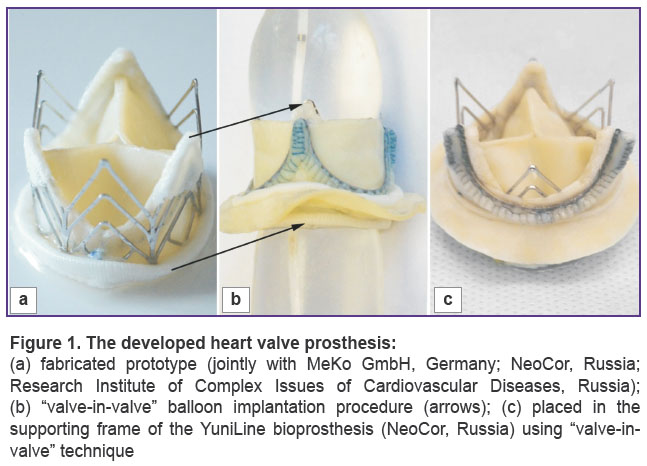 |
Figure 1. The developed heart valve prosthesis: (a) a fabricated prototype (jointly with MeKo GmbH, Germany; NeoCor, Russia; Research Institute of Complex Issues of Cardiovascular Diseases, Russia); (b) “valve-in-valve” balloon implantation procedure (arrows); (c) placed in the supporting frame of the YuniLine bioprosthesis (NeoCor, Russia) using “valve-in-valve” technique |
Models for a full range of prostheses typical sizes from 19 to 33 (a total of 8 models) were studied. A supporting frame of the given prosthesis represents a construction of a cylindrical form, the walls of which have a cellular structure of open and closed type. The supporting frame is fabricated by laser cutting of a tube with a specified thickness and diameter from AISI 316L medical grade stainless steel (Figures 1, 2). A mechanical material properties were described by an elastic-plastic model with isotropic hardening. Strength and fatigue characteristics of the material are given in the Table [12].
|
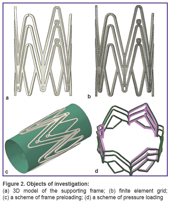
Figure 2. Objects of investigation:
(a) 3D model of the supporting frame; (b) finite element grid; (c) a scheme of frame preloading; (d) a scheme of pressure loading |
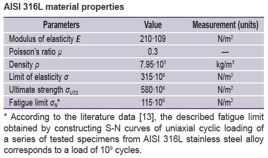 |
AISI 316L material properties |
Finite element analysis. Investigations were carried out in the engineering analysis medium SIMULIA Abaqus (USA). Initial CAD models of the supporting frames were imported to the pre/post processor Abaqus/CAE and approximated by 3D eight-node finite elements with full integration (C3D8R). An overall dimension of the finite element model was 48,576 elements with average linear sizes of 0.125×0.125×0.125 mm.
Under working conditions, a heart valve prosthesis is subjected to two main types of action: by a balloon during implantation procedure (Figure 1 (b)) and loads in the implanted state (Figure 1 (c)) due to a blood flow action in the diastole–systole cycle. In the former case of action, the supporting frame is imparted a working, implanted, geometry, changing its initial diameter (15 mm) to the final one (19–33 mm) using balloon technology. In the course of this procedure, accumulation of plastic deformation and fixation of the working geometry take place. As a result of the implantation procedure, the supporting frame has a non-zero strain-deformed state connected with the work of the construction in the elastic-plastic zone, which significantly influences the subsequent assessment of the fatigue strength [14, 15]. The effect of a cyclic load occurs under the pressure of the blood flow on the supporting frame and on the leaflet apparatus, it cannot cause an essential elevation of the average pressure, but its influence is significant on conversion to a large quantity of cycles (200 million). As the supporting frame during its life cycle is subjected to the two types of action, implantation and cyclic load, the study was performed in two consecutive stages. The first stage was implantation modeling. It consisted of two steps:
expansion of the tested model by a balloon, having a cylindrical surface from 2,200 elements of SFM3D4 type, to a specified external diameter;
application of the reverse load to the balloon for the evaluation of the recoil-effect of the construction and formation of the final stress-strained condition of the system.
The second stage was the assessment of fatigue strength, loading the models with a blood flow equivalent. The pressure applied to the inner frame wall in the region of commissural posts was used as a load. Fatigue strength was tested under normal and hypertensive pressure at 70 beats per min. The character of pressure application corresponded to the pressure for aortic (for 19–25 mm prostheses) and for mitral (27–33 mm prostheses) positions: in case of normotensive pressure, the pressure equivalent was equal to 80 and 120 mm Hg; in case of hypertensive pressure it was 110 and 180 mm Hg. Taking in the consideration the specificity of implantation of the tested object (into the frame of the incompetent prosthesis), all radial movements outwards from the central axis were limited, i.e. a repeating cycle of regular loading with a coefficient of skewness R=0 was used.
Analyzed parameters. At the first stage of the investigation, von Mises equivalent stresses, being a typical characteristic for plastic materials, were used. Additionally, radial movements at maximal frame opening and after load removal were evaluated for calculation of the relative values of construction return under the action of the elastic strain component, i.e. resilient recoil.
Fatigue strength was assessed using Goodman diagram recommended by FDA for the analysis of this kind [13–15]. This method realizes the concept of infinite fatigue life (IFL). The following characteristics of a working cycle are registered: mean stress σm and alternating stress within one cycle σа. To build a diagram, data on ultimate strength σUTS and fatigue limit σN are required:
σа/σN+σm/σUTS=1.
Goodman factor was calculated and its distribution over the finite element device model was defined to be able to assess the most critical construction elements in terms of the fatigue strength.
Results
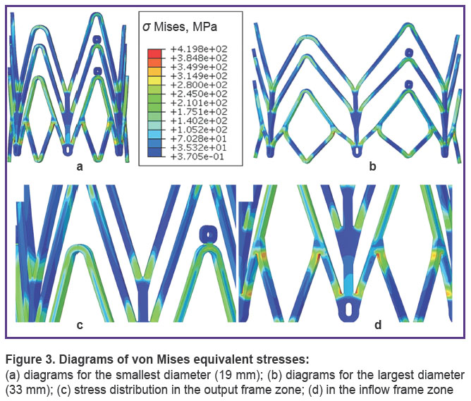
Implantation. During implantation of the supporting frame, a significant growth of mechanical stress was identified in the corners of the cells with the formation of elastic-plastic hinges. Maximal strain values were fixed for the construction of the largest dimension of 33 mm, the minimal values were fixed for 19 mm size (419.8 and 307.3 MPa, respectively). It should be noted that the most loaded nodes were located in the inflow zone of the prosthesis (Figure 3).
|
Figure 3. Diagrams of von Mises equivalent stresses:
(a) diagrams for the smallest diameter (19 mm); (b) diagrams for the largest diameter (33 mm); (c) stress distribution in the output frame zone; (d) in the inflow frame zone |
Recoil-effect observed after removing the load from the supporting frame was insignificant for both large and small construction diameters, and ranged from 4.2 to 4.48%.
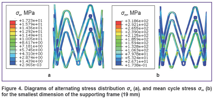
Assessment of fatigue strength. The analysis of the supporting frame fatigue strength has demonstrated insignificant values of alternating stress, the parameter determined by pressure modeling in the loading–unloading cycle (σa). The maximal value of 17.2 MPa for this parameter was observed at a hypertensive pressure for 19 mm dimensions (Figure 4 (a)), the minimal value of σa was 6.3 MPa. The parameter characterizing a total stress generating due to implantation and the effect of alternating load, i.e. mean cycle stress, was equal to 314.6–425.0 MPa (Figure 4 (b)).
|
Figure 4. Diagrams of alternating stress distribution σa (a), and mean cycle stress σm (b) for the smallest dimension of the supporting frame (19 mm) |
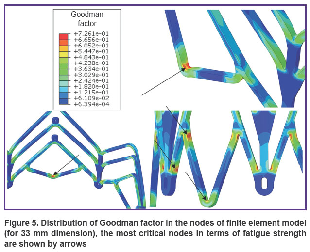
Goodman factor and its distribution on the diagrams enabled us to characterize the presence and location of the most critical points of the supporting frames. Maximal values of this parameter were within the range from 0.46 to 0.72. The diagrams demonstrated the location of the nodes with a high factor value in the zones of joints and bends of the construction (Figure 5).
|
Figure 5. Distribution of Goodman factor in the nodes of finite element model (for 33 mm dimension), the most critical nodes in terms of fatigue strength are shown by arrows |
Discussion
Implantation. The analysis of construction behavior in the process of implantation has demonstrated a significant increase of stresses in the element nodes (to 419.8 MPa) with a transition to the zone of plastic deformation, i.e. with a great excess of elasticity limit (330 MPa). However, this effect is anticipated, since the described stress growth higher the elasticity limit allows the balloon-expanded constructions to preserve and maintain their geometry after load removal, i.e. balloon action. On the other hand, the obtained von Mises stress values of 419.8 MPa (for 33 mm) in the most critical case did not exceed the ultimate strength of the material σUTS=670 MPa, i.e. they did not cause irreversible damages and cracks or microcracks development. On the basis of the described results, the process of radial frame expansion by a balloon during implantation may be supposed to be safe for the construction. At the same time, the recoil-effect typical for all balloon expandable stent-like constructions [16, 17], amounting in the process of work up to 4.48% of the final diameter, may introduce some changes in the selection of frame dimensions for implantation.
The qualitative analysis of von Mises stress distribution on the diagrams in the tested supporting frames has shown its nonuniformity: the least loaded nodes are located in the output frame zone. Such zone distribution is anticipated as the cells in the output part of the frame have longer bars and fewer junction nodes (See Figure 1 (a)).
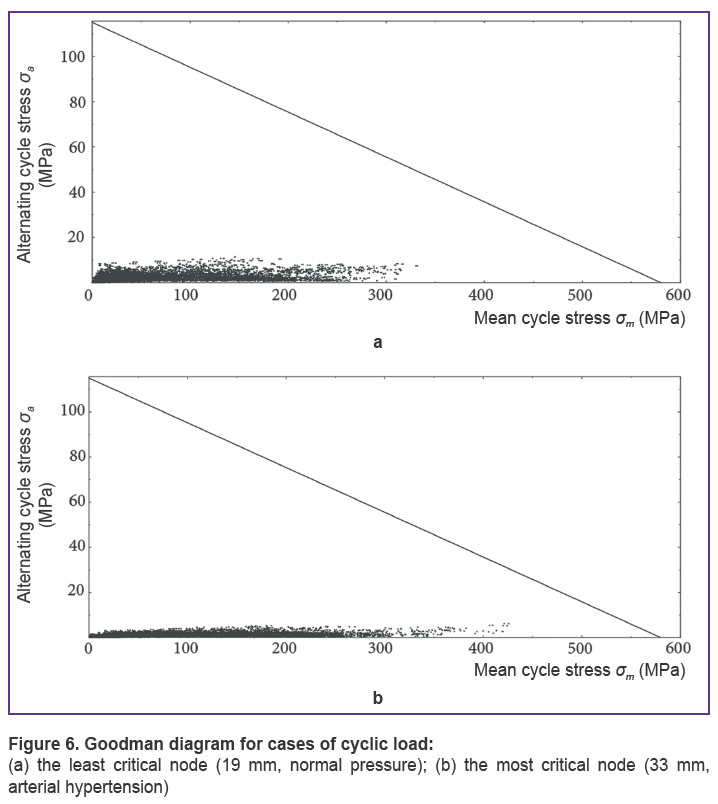
Assessment of fatigue strength. The analysis of alternating stress in the loading–unloading cycle σa, as well as mean stress in the supporting frame σm showed that these parameters were significantly lower than fatigue limit σN=278 MPa and material ultimate strength σUTS=670 MPa, i.e. they did not cause damages in the construction during 109 cycles. This conclusion is also confirmed by Goodman diagram: the analysis of fatigue strength for various modes has demonstrated inability of the constructions to exceed the border of IFL area, including the conditions of modeling arterial hypertension. It means that all nodes of the supporting frame are in the zone of IFL (below the line, Figure 6) and are capable of withstanding a load of 109 cycles.
|
Figure 6. Goodman diagram for cases of cyclic load: (a) the least critical node (19 mm, normal pressure); (b) the most critical node (33 mm, arterial hypertension) |
The qualitative analysis of Goodman diagrams showed that the stress in the construction corners is distributed nonuniformly depending on the dimensions. Thus, the nodes on the diagram for the smallest dimension (19 mm) are situated more compactly along the X-axis, that is, they have greater uniformity by the mean cycle stress parameter σm. At the same time, the nodes are located widely along the Y-axis, that is that the alternating stress σa exerts greater effect on the constructions of small diameters. Inverse relation is observed for large dimensions (Figure 6 (b)).
Thus, the contribution of the parameter tested in the first stage (frame implantation) to the stressedly-deformed state is greater for large dimensions, as it essentially increases the mean cycle stress σm. The contribution of the cyclic load itself is greater in case of small frames, as it increases the alternating stress σa.
The presence of Goodman factor with high values (up to 0.72) in the elements of the construction nodes indicates to a significant nonuniformity of stress distribution in the supporting frame, i.e. to the presence of critical nodes. However, this factor does not exceed 1.00, the border of the IFL. Despite the safety of these elements in terms of fatigue strength, design correction and decrease of the maximal value of this factor for the construction can additionally make the application of the prosthesis safer.
Conclusion. The results of the investigation based on Goodman diagrams have demonstrated that the developed stent-like design of the prosthesis supporting frame, intended for “valve-in-valve” redo-replacement of the incompetent prosthesis, provides fatigue life of not less than 109 cycles. The frame geometry combining open and closed cells allows irregular load distribution depending on the functional designation of the zones. The described method of the fatigue strength analysis can be applied for calculation of the reliability of heart valve prosthesis constructions based on the stent frames.
Study Funding. The work was supported by the grant of the Foundation for Assistance to Small Innovative Enterprises as the first stage of project 22744 “The artificial heart valve designed for “valve-in-valve” implantation”.
Conflicts of Interest. The authors have no conflicts of interest to disclose.
References
- Beckmann A., Funkat A.-K., Lewandowski J., Frie M., Ernst M., Hekmat K., Schiller W., Gummert J., Cremer J. Cardiac surgery in Germany during 2014: a report on behalf of the German Society for Thoracic and Cardiovascular Surgery. Thorac Cardiovasc Surg 2015; 63(4): 258–269, https://doi.org/10.1055/s-0035-1551676.
- Brown J.M., O’Brien S.M., Wu C., Sikora J.A.H., Griffith B.P., Gammie J.S. Isolated aortic valve replacement in North America comprising 108,687 patients in 10 years: changes in risks, valve types, and outcomes in the Society of Thoracic Surgeons National Database. Thorac Cardiovasc Surg 2009; 137(1): 82–90, https://doi.org/10.1016/j.jtcvs.2008.08.015.
- Nishimura R.A., Otto C.M., Bonow R.O., Carabello B.A., Erwin J.P. 3rd, Guyton R.A., O’Gara P.T., Ruiz C.E., Skubas N.J., Sorajja P., Sundt T.M. 3rd, Thomas J.D.; ACC/AHA Task Force Members. 2014 AHA/ACC guideline for the management of patients with valvular heart disease: executive summary: a report of the American College of Cardiology/American Heart Association Task Force on Practice Guidelines. Circulation 2014; 129(23): 2440–2492, https://doi.org/10.1161/cir.0000000000000029.
- Klyshnikov K.Yu., Ovcharenko E.A., Kudryavtseva Yu.A., Barbarash L.S. “Valve-in-valve” reprosthesing of cardiac artificial valves. Russian Journal of Cardiology 2016; 11(139): 73–80, https://doi.org/10.15829/1560-4071-2016-11-73-80.
- Balsam L.B., Grossi E.A., Greenhouse D.G., Ursomanno P., DeAnda A., Ribakove G.H., Culliford A.T., Galloway A.C. Reoperative valve surgery in the elderly: predictors of risk and long-term survival. Ann Thorac Surg 2010; 90(4): 1195–1201, https://doi.org/10.1016/j.athoracsur.2010.04.057.
- Maganti M., Rao V., Armstrong S., Feindel C.M., Scully H.E., David T.E. Redo valvular surgery in elderly patients. Ann Thorac Surg 2009; 87(2): 521–525, https://doi.org/10.1016/j.athoracsur.2008.09.030.
- AL-Mangour B., Mongrain R., Yue S. Coronary stents fracture: an engineering approach (review). Materials Sciences and Applications 2013; 4(10): 606–621, https://doi.org/10.4236/msa.2013.410075.
- Lewitton S., Babaev A. Superficial femoral artery stent fracture that led to perforation, hematoma and deep venous thrombosis. J Invasive Cardiol 2008; 20(9): 479–481.
- Scheinert D., Scheinert S., Sax J., Piorkowski C., Bräunlich S., Ulrich M., Biamino G., Schmidt A. Prevalence and clinical impact of stent fractures after femoropopliteal stenting. J Am Coll Cardiol 2005; 45(2): 312–315, https://doi.org/10.1016/j.jacc.2004.11.026.
- Ghawi H., Kenny D., Hijazi Z.M. Transcatheter pulmonary valve replacement. Cardiol Ther 2012; 1(1): 5, https://doi.org/10.1007/s40119-012-0005-9.
- GOST 31618.1-2012 Protezy klapanov serdtsa. Chast’ 1. Obshchie tekhnicheskie trebovaniya i metody ispytaniy [GOST 31618.1-2012 Cardiac valve prostheses. Part 1. General technical requirements and test methods]. 2015.
- Wiersma S., Dolan F., Taylor D. Fatigue and fracture in materials used for micro-scale biomedical components. Biomed Mater Eng 2006; 16(2): 137–146.
- Tabanli R.M., Simha N.K., Berg B.T. Mean strain effects on the fatigue properties of superelastic NiTi. Metall and Mat Trans A 2001; 32(7): 1866–1869, https://doi.org/10.1007/s11661-001-0164-0.
- Forrest P. Ustalost’ metallov [Fatigue of metals]. Moscow: Mashinostroenie; 1968; 352 p.
- Berendeev N.N. Soprotivlenie ustalosti. Osnovy [Resistance to fatigue. Fundamentals]. Nizhny Novgorod: Nizhegorodskiy gosuniversitet; 2010; 64 p.
- Ohya M., Kadota K., Kubo S., Tada T., Habara S., Shimada T., Amano H., Izawa Y., Hyodo Y., Otsuru S., Hasegawa D., Tanaka H., Fuku Y., Goto T., Mitsudo K. Incidence, predictive factors, and clinical impact of stent recoil in stent fracture lesion after drug-eluting stent implantation. Int J Cardiol 2016; 214: 123–129, https://doi.org/10.1016/j.ijcard.2016.03.013.
- Kitahara H., Waseda K., Yamada R., Otagiri K., Tanaka S., Kobayashi Y., Okada K., Kume T., Nakagawa K., Teramoto T., Ikeno F., Yock P.G., Fitzgerald P.J., Honda Y. Acute stent recoil and optimal balloon inflation strategy: an experimental study using real-time optical coherence tomography. EuroIntervention 2016; 12(2): e190–e198, https://doi.org/10.4244/eijv12i2a32.